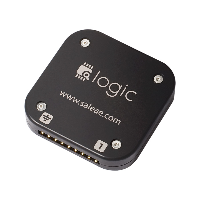
 One of the best investments I have made recently has been on an 8 channel Saleae Logic analyzer. The 16 channel unit was unfortunately outside of my budget. The current version of the software that drives the logic analyzer is Logic 1.1.15. It comes with multiple protocol analyzers for serial, parallel, I2C and others. While integrating an LCD display based on the ubiquitous HD44780 to an ATTINY2313 microcontroller, I needed to debug the initialization sequence of the driver I was using. Using the parallel protocol analyzer that comes with the Logic software can do the job, but requires painful analysis of each line and going back and forth to the data sheet to translate hex codes to commands. As a result of this effort I have created a HD44780 protocol analyzer for the Saleae Logic/Logic 16 products. The rest of this post documents the features of the protocol analyzer and how to install it and take it for a quick spin.
Analyzer Features
The HD44780 Protocol Analyzer supports three modes of analysis in order to balance the type of device you have (Logic or Logic 16) with the different programming modes of the HD44780. The 11 bit mode, requires 8 channels for data and 3 channels for control. This mode is only supported in the Logic16 device, since it requires 11 channels. It analyzes communication with the HD44780 using 8 channels for data.
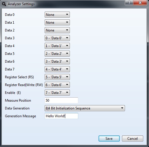
The 8 bit mode, uses 3 channels for control and 5 channels to supports analysis of 8 channels of data. In this mode the first 3 bits of the data byte are not captured. It allows owners of the Logic (8 channels) device to operate in virtual 11 bit mode. The analyzer compensates for the missing three bits by displaying possible combinations for the captured data. For instance, while sending the letter ‘A’, binary 01000001, to the HD44780, the analyzer only sees 01000. It performs all the combinations for the three missing bits and when displaying the message for this data it shows Write(@,A,B,C,D,E,F,G). This mode is selected by indicating the first three channels of data are ‘None’ in the configuration screen. This mode is supported in both the Logic and Logic 16 devices.
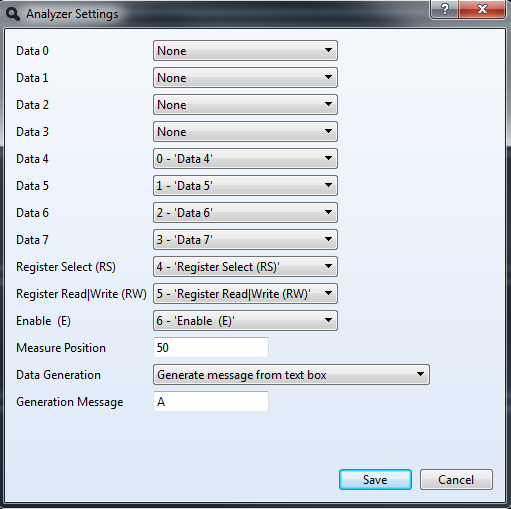
The 7 bit mode, uses 3 channels for control and 4 channels for data. This mode is supported in both the Logic and Logic 16 devices and correspond the 4 bit data mode of the HD44780. This mode is selected by indicating the first four channels of data are ‘None’ in the configuration screen.
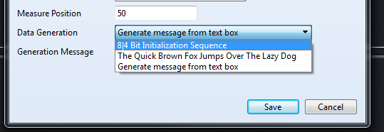
The position within the enable pulse where the signal for all channels is measured can be controlled between 0 and 99%. This has come handy while analyzing code that checks for the busy flag in a tight loop as opposed to providing multiple requests to read the busy flag. The analyzer can generate three types of test patterns. An initialization sequence, the text “The Quick Brown Fox Jumps Over The Lazy Dog” or you can type your own text in the provided text box. These data generation options are helpful while testing the analyzer without the Logic or Logic 16 connected to the computer. Let’s install the analyzer and perform a quick test.
Installation
The binary file and source code are located at Codeplex in the HD44780 Protocol Analyzer project. Download the binary file from the download area, unzip it and copy to HD44780Analyzer.dll to the Analyzer directory of the Logic 1.1.15 installation. In my Windows 7 PC this directory is located at “C:\Program Files\Saleae LLC\Analyzers”. Note this release of the analyzer is only for windows. Porting it to Linux and Mac should not be a complicated task. Once you have copied the file, launch the Logic 1.1.15 software and under the Analyzer menu on the right hand side of the screen you should see HD44780-V1.0.0.1. The V1.0.0.1 corresponds to the version of the dll.
Configuration
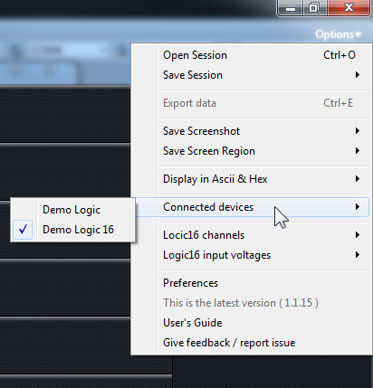
To get started testing the HD44780 Protocol Analyzer, make sure your Logic/Logic 16 is not connected to your computer. This will allow you to select a demo Logic/Logic 16 device and run the simulations contained in the code. From the options menu select Connected Devices/Demo Logic 16.
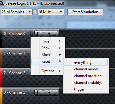
On the first channel, select the option to reset everything, this will clear up any custom names you may have on your channels and make all 16 channels visible. Hide all channels below channel 10, only channels 0-10 are needed.
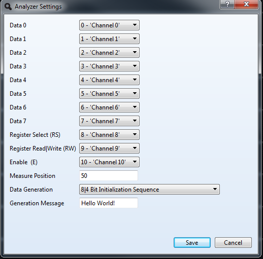
Edit the settings of the analyzer and make sure all data channels look like that of picture 1 and the Data Generation option is set for 8|4 Bit Initialization Sequence. Save the settings and select the option to rename the channels, this makes the analysis easier. Select 2 M Samples at 16Mhz and click the Start Simulation button at the top of the screen. Note the Start Simulation option is only available when the device is not connected.
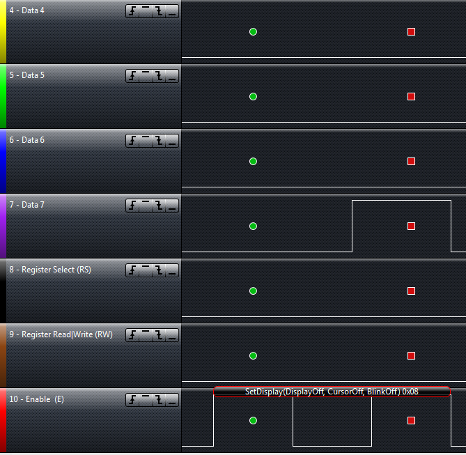
Zoom in on the first command sent to the HD44780 and you should see the information depicted in figure 8.
The name of the function and its parameters are displayed in a bubble on the enable (E) channel. SetInterface commands sent as part of the first 5 commands are considered initialization commands and marked with the icon with the number 1 in a circle. The location of the icon indicates the position in the pulse where all the channels are measured. Table x illustrates the text displayed by the analyzer for the different commands supported by the HD44780.
[table “20” not found /]In 7 bit mode, the start frame and end frame are properly identified with a green circle and a square red dot. The text bubble is displayed over both frames. Changing the measure position in the setting interface moves the frame marking accordingly. There is also minimalistic error tracking in 7 bit mode to detect if the control lines are different between the transmission of the first and second nibble of data to the HD44780.
Data Export
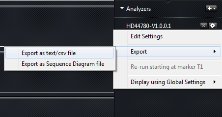
This version of the analyzer allows exporting the captured data to two different types of reports. The first report generates a CSV file so you can manipulate the raw data for each captured frame in a spreadsheet.
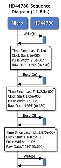
The second report generates the commands for a sequence diagram that you can plugin at websequencediagrams and generate a graphical representation of the commands. Figure 11 illustrates a portion of the sequence diagram generated for the message Hello World! in 11 bit mode.
Testing
I have tested analyzing the HD44780 protocol in 7 and 8 bit modes using the HD44780 Library by SA Development from AVRFreaks forum. If you are the lucky owner of a Logic 16 and can test an implementation of an LCD driver and provide feedback on the result, it would be greatly appreciated. I am planning on testing the Arduino LiquidCrystal library as well to validate the code behaves as expected.
Future Release
That’s all for this release. In a future release I am considering adding an HTML report with some options to replay the captured stream. There are also opportunities for enhancing the detection of the initialization sequence and reporting when the commands or signal timing is outside of the specs provided by the datasheet.

