Attaching components to an I2C bus can be a tedious experience when things do not go right. Many factors ranging from bus termination, cross over cables and faulty devices can drive you to drink while debugging a problem. I have been using a PDE created by Tod E. Kurt to perform bus scanning when troubleshooting connectivity to I2C components. This post discusses modification made to the code provide by Tod and its conversion to an Arduino library. The I2CScanner class is meant to be used as a debugging tool. It assumes the bus is operational. This class has little value if you are trying to bit bang an implementation of the I2C protocol. The class satisfies two primary use cases. Scanning the I2C bus and displaying the status of each address and determining if a device is listening to a particular address.
Installation
The following steps describe how to download and install the library.
- Download the file i2cscanner.zip and unzip to a temporary directory. It contains the files i2cscanner.h, i2cscanner.cpp and i2cBusScannerDemo.pde.
- Create a directory named i2cscanner in the library directory of your Arduino installation.
- Copy the files i2cscanner.h and i2cscanner.cpp to the newly created i2cscanner directory.
- Load the pde and run
Using The Library
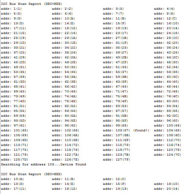
Listing 1 contains the code of a demo PDE that tests the different methods of the class. The method I2CScanBus::isAddressOnBus(byte address) has been very helpful while creating unit tests to test code that interface with I2C components. The other method of the class, scanBus(..) and its overloads, allow finer control of the range of addresses to include and how to display the report generated when the I2C bus is scanned.
#include <Wire.h>
#include <i2cscanner.h>
using Utilities::I2CScanBus;
void setup()
{
/* Initialize libraries */
Wire.begin();
Serial.begin(19200);

/* Scan I2C bus from address 1 - 127 */
I2CScanBus::scanBus();

/* Check if there is a device at address 103 */
Serial.print("\nSearching for address 103...");
if ( I2CScanBus::isAddressOnBus(103) )
Serial.println("Device Found");
else
Serial.println("Device NOT Found");

/* Scan I2C bus from address 10-20 */
I2CScanBus::scanBus(10,20);

/* Scan I2C bus from address 1 - 127, display addresses in HEX using two columns */
I2CScanBus::scanBus(1,127, I2CScanBus::NUM_HEX, I2CScanBus::TWO_COLUMN);
}

void loop()
{

}
Figure 1, shows the partial output of the report generated by running the code in the sample pde. Addresses are displayed in decimal and hex. Option to display the address in binary or octal is available as well.
Once you have the sample sketch setup you can run it any time you need to scan the bus. Alternatively you can reference the library and scan the bus from within your project as needed.

