The Arduino core libraries provide a well defined structure for developing code with the different micro-contollers it supports, but not every project requires the power provided by the ATMega 328 or 2560 chips. Simple projects can take advantage of the ATTiny family of micro-controllers. The goal of this post is to demonstrate how to use Arduino Template Express (ATE) to deploy the Arduino Core libraries to the ATTiny family of micro-controllers. This post will show you how to setup a development board with the ATTiny85 micro-controller and enable it with serial communication capabilities and the ability to use the Arduino Core libraries. In order to follow this tutorial, you will need the following:
- Atmel Studio 6.1 or greater
- Arduino Template Express (ATE) 1.0.2 or greater
- An ISP programmer – I will use AVRISP-MKII and AVR Dragon to demonstrate deploying code with either programmer. If you have an Arduino based ATTiny programmer, that is also fine.
- FTDI Breakout Board – The FTDI Basic Breakout from SparkFun or the FTDI Friend + extras from Adafruit will do the job. I will use FTDI Basic Breakout from SparkFun to allow the ATTiny85 to send serial information to a terminal. If you are creative and do not have access to a FTDI Breakout board, you can remove the ATMega328 chip from an Uno board and use the serial communication capabilities already included in the board as a substitute for the FTDI Breakout board.
- An ATTiny85 assembled on a breadboard or from a development board such as the one provided by Tinkerlog.
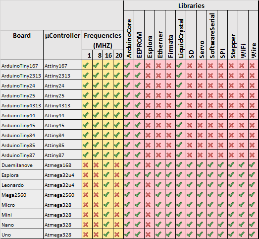
Although, I will use an ATTiny85, the instructions applies to any of the ATTiny micro-controller for which ATE provides a compiled Arduino core library. Figure 1, contains a list of supported micro-controllers.
Hardware Configuration
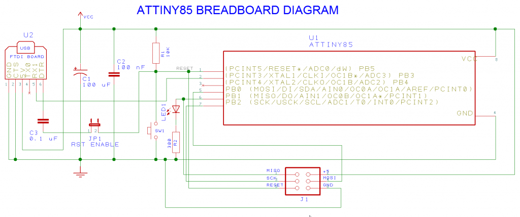
Let’s begin by configuring the development board. Figure 2, contains the schematic diagram of the minimum configuration needed to run an ATTiny85. This configuration uses the internal 8 MHZ clock to drive the micro-controller. In order to transfer data to the FTDI breakout board, pin 2 of the micro-controller is connected to the TX pin of the FTDI breakout board. The 5V supplied by the FTDI breakout board on pin 3 provide power to the micro-controller. Jumper JP1 is used to enable/disable resetting the micro-controller when a terminal connection is made to the FTDI breakout board. Jumper JP1 should be open when using the AVR Dragon to debug sketches. If connected, the capacitor C3 causes side effects while stepping through the code. By the way, having this jumper on the original Uno board would be a welcome feature. Note the CTS pin of the FTDI breakout board is connected to ground to prevent the FTDI chip from stopping the transmission.
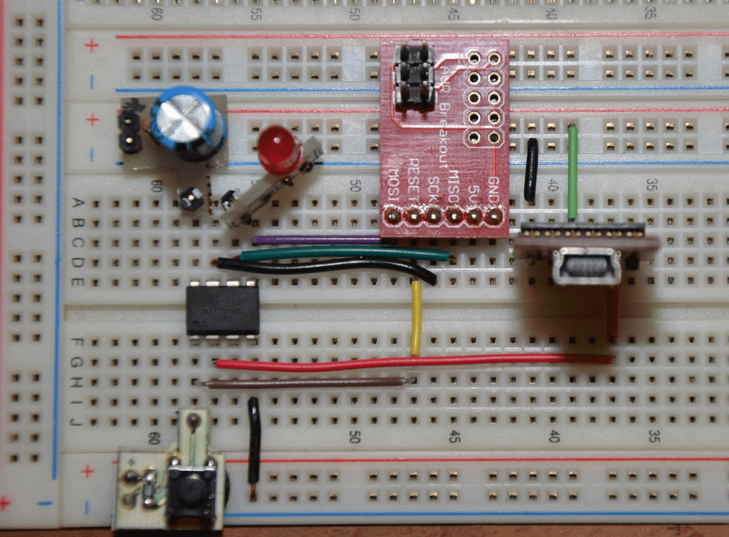
Figure 3 contains a breadboard implementation of the design. Note the usage of breadboard helpers to speed up the assembly of the circuit.
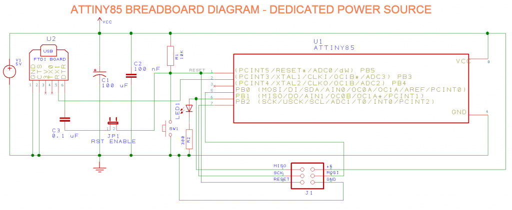
The FTDI breakout board comes in 5V and 3.3V flavors. Breakout boards with more advance features have a jumper that controls the voltage output and can be switched between 3.3V and 5V. If you happen to have a 3.3V FTDI breakout board, you will need to introduce an external power supply to drive the circuit. Figure 4 contains a circuit diagram that uses an external power supply to provide power to the micro-controller. Note the 3.3V pin of the FTDI breakout board is not connected to the micro-controller.
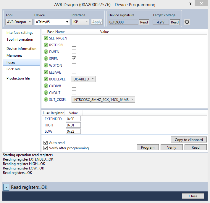
The circuits illustrated in figure 2 and 4 are functionally equivalent, the only difference is how the micro-controller is powered. It is important to note that in order for the ISP programmer to work, the micro-controller needs to be connected to an independent power source. Both, the 5V provided by the FTDI breakout board or an external power supply will satisfy this requirement. Before proceeding connect the ISP programmer to the ISP header (J1) and configure the micro-controller fuses. Table 1 contains a list of the values of the different fuses that need to be programmed.
[table “22” not found /]
If you need information abut AVR fuses check Lady Ada tutorial on her site. Figure 5 illustrates the Atmel Studio screen from where the fuses are programmed. See (Tools/Device Programming) or (Ctrl+Shift+P).
At this point we have a development board assembled in a breadboard. The following step is to register the board in Arduino Template Express so the wizard can pick it up when new projects are created.
How ATE Supports Multiple Boards
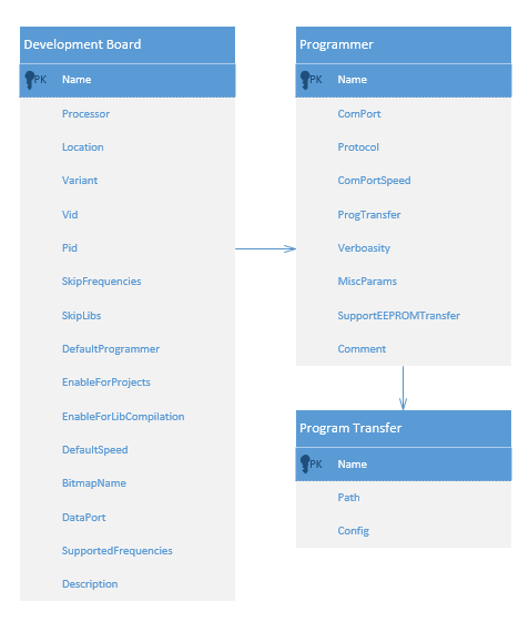
ATE uses the concept of a development board as an abstraction of the environment for which a developer creates code. Figure 6, illustrates an entity diagram of a development board.
Each development board has a series of properties that identify the board. A programmer is is a logical construct that includes the port used to program the board and the application responsible for transferring the sketch created by a developer. ATE comes configured with 17 defined boards, 8 of which can be activated during installation. An activated board shows in the list of available boards when the wizard runs to create a new project. ATE supports an unlimited number of boards that can be manually added or activated after installation. In order to enable the board ArduinoTiny85 follow the following instructions:
- Open the file boards.xml with your favorite editor. I would recommend Notepad++ if you do not have a favorite editor already.
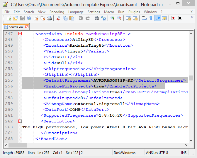
- Find the board “ArduinoTiny85”, around line 247
- Change the property <EnableForProjects> to true, it is false by default. This is the flag that tells the ATE wizard to include the board as an option.
- Change the programmer to AVRDRAGONISP-AT. Since I am using AVR Dragon and will use the ISP header and the atprogram.exe provided by Atmel. If you are using another programmer, find a suitable entry or create one. Figure 7 illustrates a modified record.
- Configure the DataPort field to reflect the Com Port that is created when you connect the FTDI Breakout Board. Check the Device Manager list of Com Ports if necessary.
- Last, locate the programmer entry AVRDRAGONISP-AT and make sure the ComPort property is set to avrdragon and the protocol to ISP. ATE 1.0.2 beta was shipped with the wrong port/protocol combination. This will be changed in the final release.
At this point we have a development board configured and registered. Let’s proceed to create a hello world sketch.
Creating Hello World
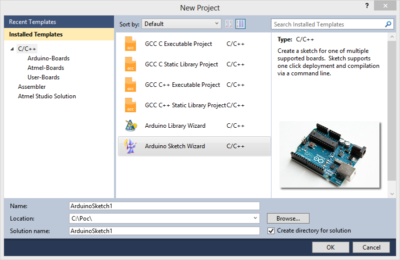
Start by launching Atmel Studio, selecting new project, and select Arduino Sketch, see figure 8. Once you press OK the ATE Wizard will start.
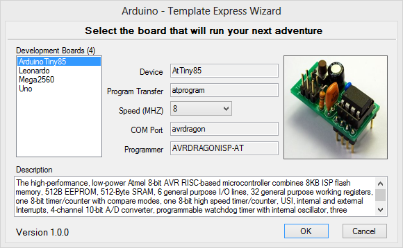
Figure 9 illustrate what the wizard will show you. The boards will vary based on what you have installed, but the ArduinoTiny85 should be in the list. Select ArduinoTiny85 and also select 8 Mhz from the supported speed drop down. Press OK and a new project will be created tailored to the Attiny85.
Compile the program and you will get two errors and 4 warnings. The errors are related to the fact the Arduino Serial library is not supported by the ATTiny85, that’s OK, let’s get rid off all Serial references and concentrate first on making the LED blink. We’ll introduce a Serial library replacement later. Comment all lines referencing Serial in main.cpp and Utility\buildinfo.cpp. Do not delete the lines, just comment them. At this point you should be able to compile the code and receive 4 warnings, but the code will compile successfully. Make sure your board has power and the programmer is connected to the ISP header. Press Deploy in Atmel Studio and see the LED start flashing. If this the LED does not flash, retrace your steps to verify everything is connected properly. It is important to note the code is Arduino friendly and you can move to any Ardunio board for which the core libraries are compiled. This means you are capitalizing on your investment to learn and use the Arduino core library. Now the LED is flashing and the code can be successfully deployed, let’s take care of the Serial connection.
Enabling Serial Connection
The TinyDebugSerial library provided as open source by Rowdy Dog Software is an implementation compatible with the Serial library provided by Arduino. It only uses one pin to transmit and does not provide data receive capabilities. Download TinyDebugSerial.cpp, TinyDebugSerial.h, TinyDebugSerial9600.cpp and core_build_options.h. Include the “TinyDebugSerial.h” in main.cpp and “..\TinyDebugSerial.h” in BuildInfo.cpp. Remember to remove the comments on the lines of code referencing Serial. Recompile and deploy the code. Open a terminal and connect to the proper COM Port and you will see output coming from the Attiny85. If you do not want to deal with all of this, a fully functional sketch is included in the link below. Download, compile and deploy. If you have configured the ArduinoAttiny85 properly in your board, the deployment script will pick all your local parameters and deploy successfully.
Download Source Code: Sketch85


I did everything like you said above but when I got to file->new project I observed that the Ok button is missing and there is no way for me to create the project
Omar,
I’m currently using your Arduino IDE libraries for Atmel Studio 6.1.
I was wondering if you know how to use the Arduino Due board with Atmel Studio 6.1?
Do you have any libraries for this?
Thanks,
Anthony
But for programming the attiny you don’t NEED the ISP programmer right? And do I have to boatload the chip in any way?
You do not need to bootload the chip but you DO NEED a programmer.
this program dont working , avr studio 6.1&6.2